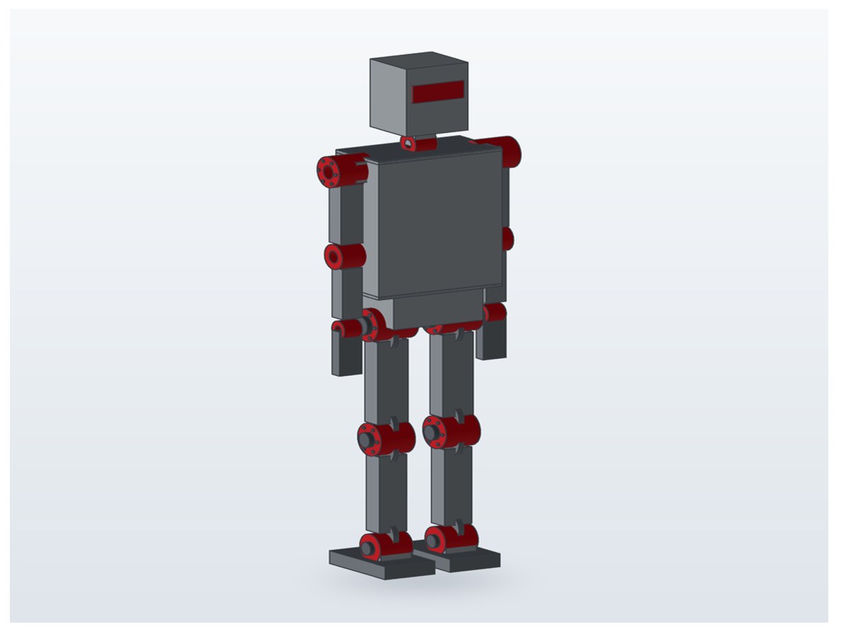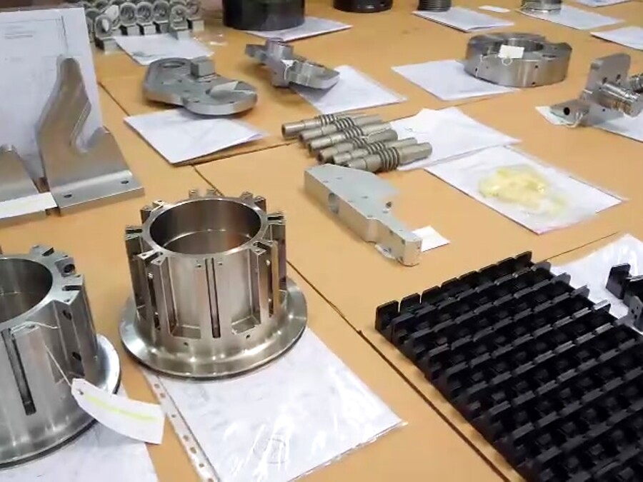


The basic structural frame of a humanoid robot — RRR Vietnam drawing set
Four A3 drawings: 12-assembly general arrangement, torso box frame, pelvis and hip housing, limb link and joint flange — with materials, tolerances and machining routes.
The hardest part of a humanoid robot is not the software — it is the frame. It carries every load, holds the joints in position and decides whether the machine walks smoothly or shakes. RRR Vietnam presents a basic structural frame drawing set that we can machine end to end in our own shop.
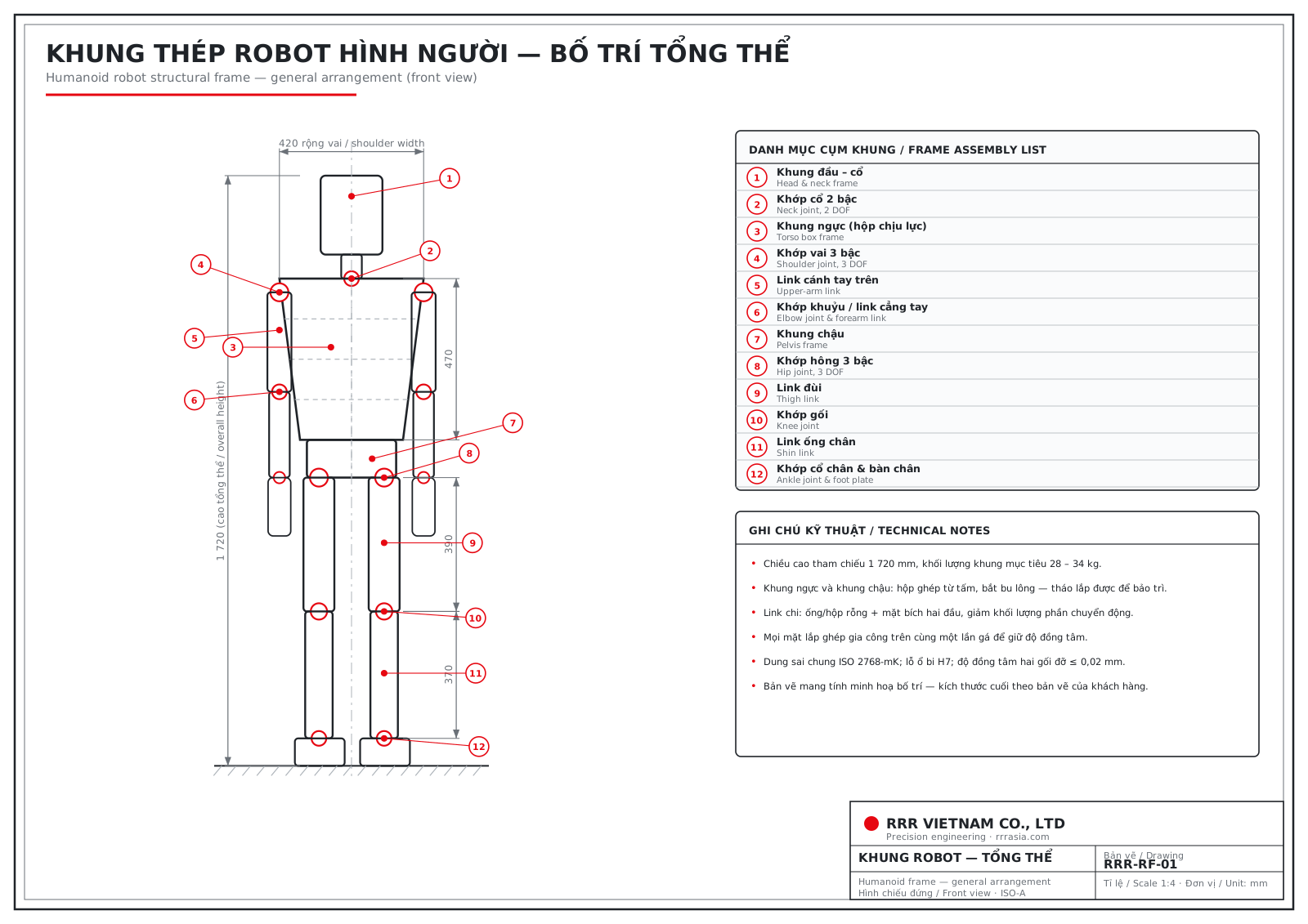
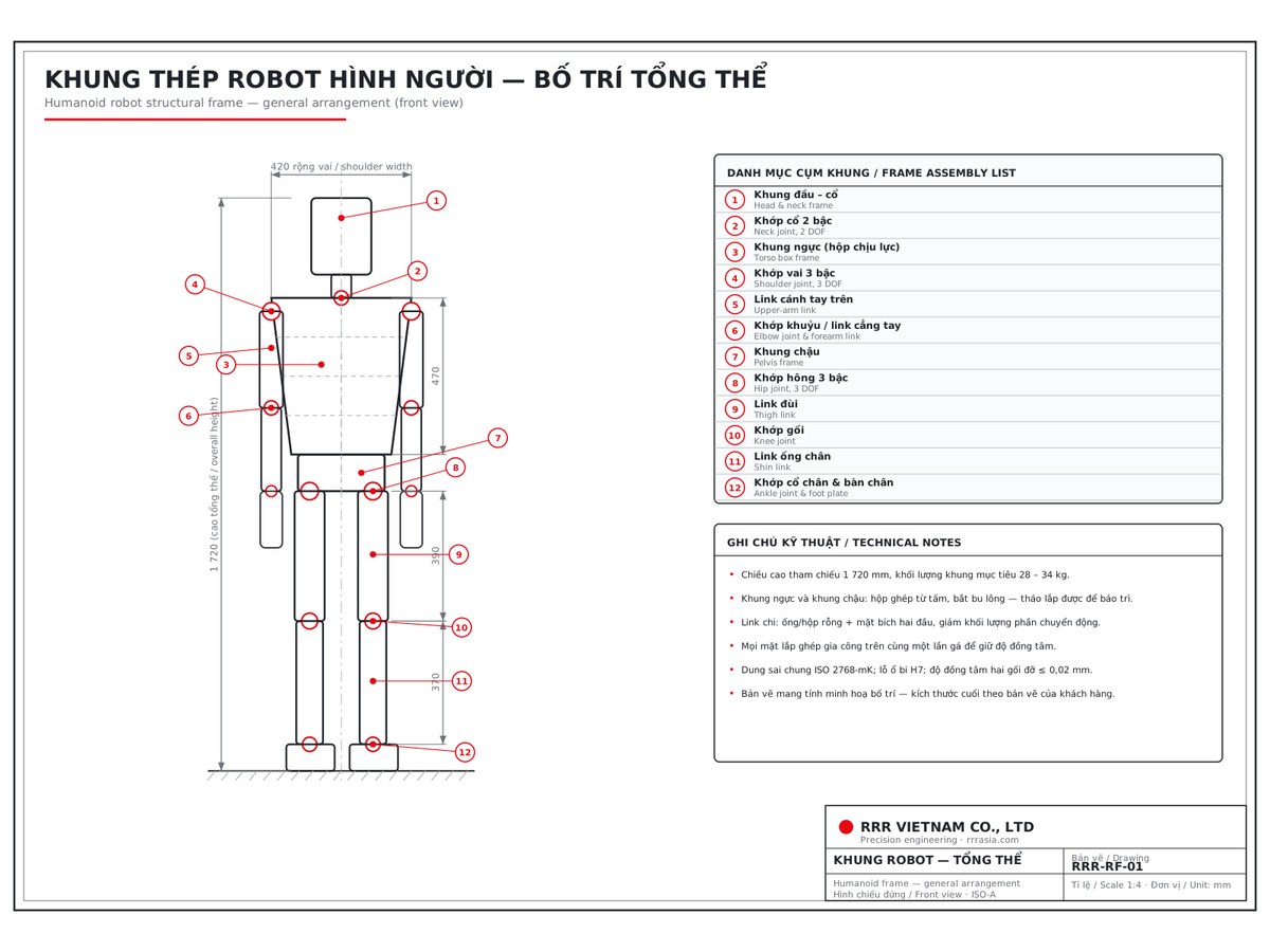
1. General arrangement
The set is laid out for a reference height of 1,720 mm, 420 mm shoulder width and 260 mm hip width. The frame is split into 12 assemblies: head and neck frame, neck joint, torso frame, shoulder joint, upper-arm link, elbow joint and forearm link, pelvis frame, hip joint, thigh link, knee joint, shin link, ankle joint and foot plate.
Target frame mass is 28 – 34 kg. One principle runs through the whole design: whatever moves most must be light — so every limb link is hollow, while the torso and pelvis are built for stiffness.
2. Torso box frame
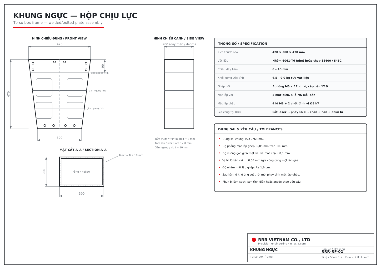
A 420 × 300 × 470 mm box built from 8 – 10 mm 6061-T6 aluminium plate, with three ribs and four lightening windows. Both shoulder faces and the pelvis mounting face are milled in a single setup so they stay square to each other.
- General tolerance ISO 2768-mK
- Flatness of mating faces 0.05 mm per 100 mm
- Shoulder hole position ± 0.05 mm
- Stress relieve after welding, then finish-mill the mating faces
3. Pelvis frame and hip joint housing
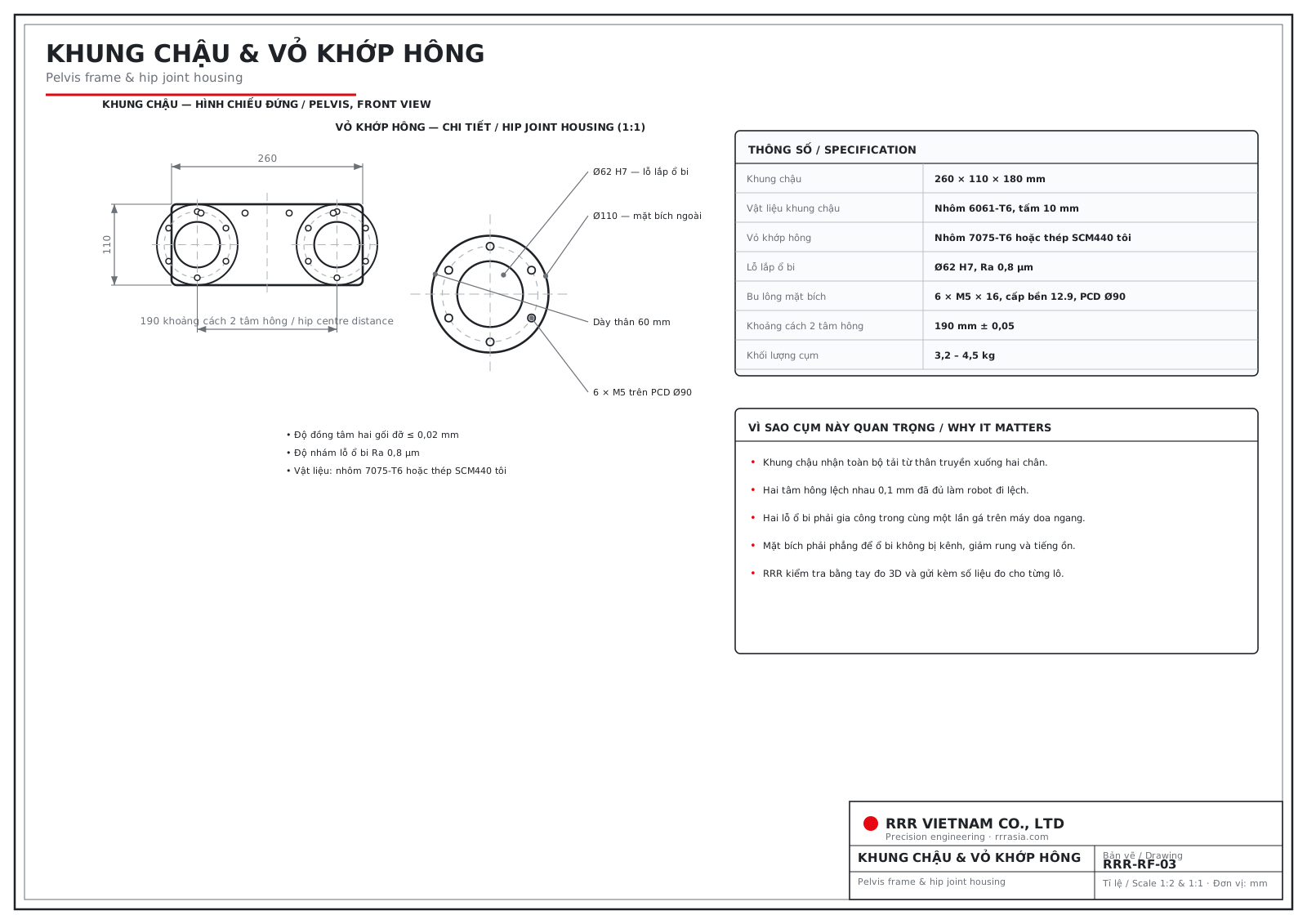
The pelvis takes the entire load from the body down into both legs. Hip centres are 190 mm ± 0.05 apart; 0.1 mm of error is already enough to make the robot walk off line. The two Ø62 H7 bearing bores are therefore machined in one setup on a horizontal boring machine, concentricity ≤ 0.02 mm, surface finish Ra 0.8 μm.
4. Limb links and joint flanges
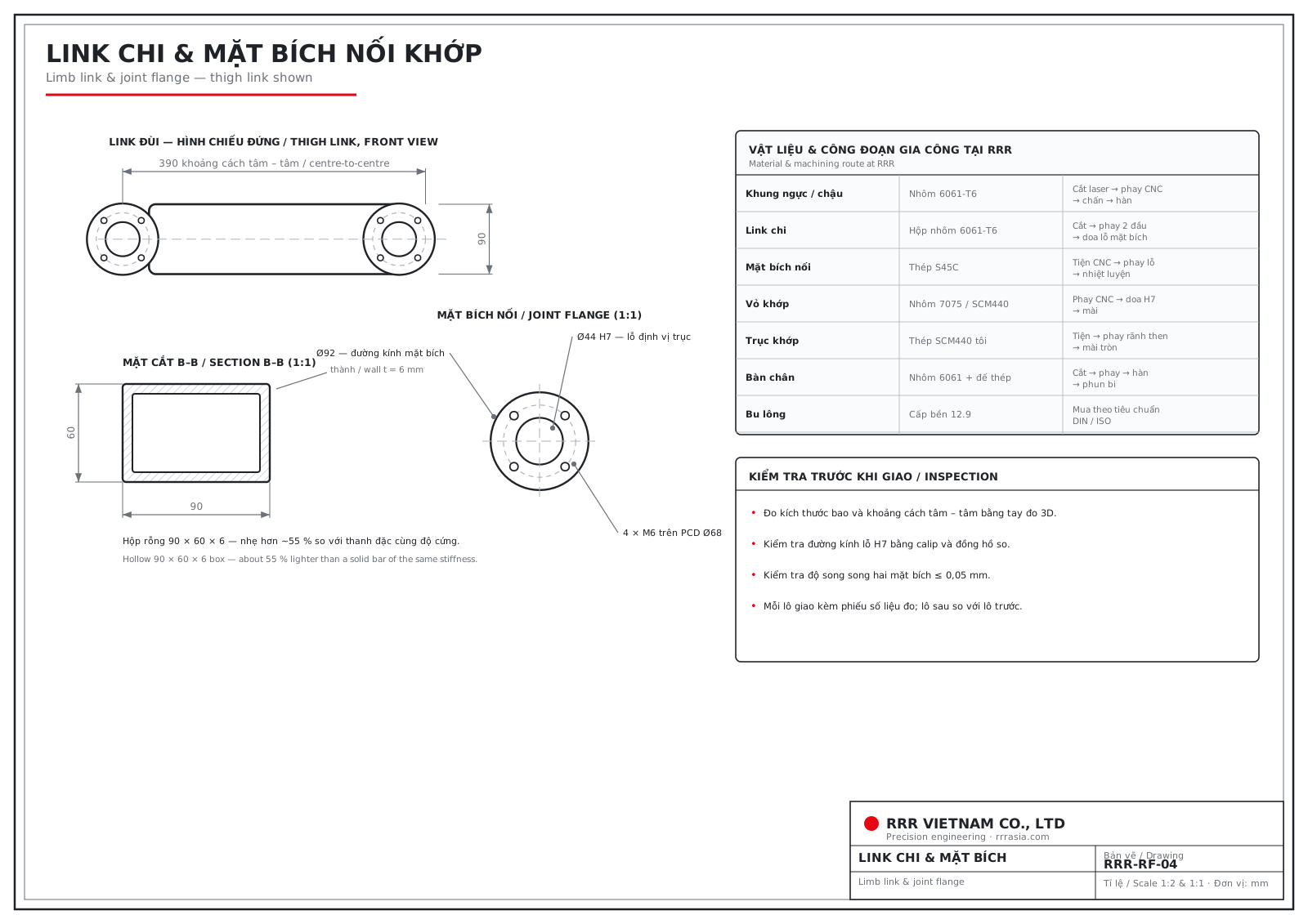
The thigh link is 390 mm centre to centre with a hollow 90 × 60 × 6 mm box section — roughly 55 % lighter than a solid bar of the same stiffness. Each end carries a Ø92 flange with a Ø44 H7 shaft location bore and 4 × M6 on a Ø68 bolt circle.
5. Materials and machining route at RRR
- Torso / pelvis — 6061-T6 aluminium: laser cutting → CNC milling → bending → welding
- Limb links — 6061-T6 box section: cutting → milling both ends → boring the flange bores
- Joint flanges — S45C steel: CNC turning → hole milling → heat treatment
- Joint housings — 7075-T6 or SCM440: CNC milling → H7 boring → grinding
- Joint shafts — hardened SCM440: turning → keyway milling → cylindrical grinding
- Foot plates — 6061 aluminium with steel sole: cutting → milling → welding → shot blasting
6. Inspection before shipping
Overall dimensions and centre distances are measured on a 3D measuring arm; H7 bores are checked with gauges and dial indicators; flange parallelism ≤ 0.05 mm. Every batch ships with its measurement record, and each batch is compared against the previous one.
Download the drawing set
Download all four drawings as PDF (A3)
This drawing set was prepared by RRR Vietnam to illustrate frame layout and our machining capability. Final dimensions always follow the customer's own drawings.
If you design robots and need the mechanical parts made, send your drawings through the quotation form on this website or contact +84 909 365 044 (Mr. Van).